注塑机 挤出机 造粒机 吹膜机 吹塑机 吹瓶机 成型机 吸塑机 滚塑机 管材生产线 板材生产线 型材生产线 片材生产线 发泡设备 塑料压延机
无锡宝帝流体控制系统科技有限公司

无锡宝帝流体控制系统科技有限公司
/product_cn/typeid/3.html
 | |||||||||||||||||||||||||||||||||||||||||||||||||||||||||||||||||||||||||||||||||||||||||||||||||||||||||||||||||||||||||||||||||||||||||||||||||||||||||||||||||||||||||||||
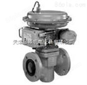
三通气动薄膜阀three-way pneumatic diaphragm valve 1. 依工作温度(℃)及适用流体来决定阀的型号。 In accordance with the working temperature (℃) and the suitable fluid to determine valve model. 2. 依流量值(KVS)来决定阀的口径。 In accordance with the flow value (KVS) to determine the valve diameter. 3. 依压力值(△P)来决定传动器的型式。 According to the pressure value (△P) to determine the type of driver. 型号(type):Baodi-240/242-B-AD-P21-3/6/12/18-Fu/Fo 形式(form):242=三通(three-way),240=三通(three-way)(分流,混合式Shunt, mixed type) 操作压力(operating pressure):3=1.2kg/cm2, 6=1.2kg/cm2, 12=1.2kg/cm2, 18=1.2kg/cm2 操作方式(mode of operation):Fu=通气开(Ventilation opening),Fo=通气关(Ventilation, close) 工作温度(working temperature):-20℃~+350℃ 本体耐压(body pressure):PN16及PN25(PN16 and PN25)(压差值参考表the reference table difference pressure) 控制方式(control mode):P.PI.PID.ON-OFF 轴封形式(the seal form):Gland 传动器耐温(motor temperature):-10℃~+80℃ 口径(Caliber):DN15~DN150mm(1/2”~6”) 流量值(flow value):参考表(reference table) 适用流体(application of fluid):蒸汽,热水,水,气体,油品(steam, hot water, water, gas,oil) 本体材料(the material of the body):碳钢/球墨铸铁(carbon steel/ductile cast iron)
Fu和Fo在外形上识别(Fu and Fo in shape recognition): Fu(如下左图):压缩空气入口在上端,通气时阀门打开,即图中A与AB畅通,在平常不通气时,A与AB之通路是关闭的,故称常关(OPG). Fu(Below, the picture on the left):Compressed air entrance at the upper end, ventilation valve open, namely A and AB map is smooth, usually is not ventilation, A signaling pathway with AB is closed, so that the normally closed (OPG) Fo(如下右图):压缩空气入口在下端,通气时阀门关闭,即图中A与AB不通,在平常不通气时,A与AB之通路是畅通的,故称常开(OPO). Fo(Below, the picture on the right):Compressed air entrance at the lower end, close the valve when the ventilation, namely A and AB barrier in the picture, in the usual no ventilation, A and AB channel is unimpeded, so normally open (OPO).
【控制阀之公称直径(DN)及流量值(KVS)】 【control valve nominal diameter (DN) and flow value (KVS)】
混合式控制及配管方式(Hybrid control and Piping manner)
1 控制阀在安装时,不论是混合式控制或是分流式控制,其安装位置请尽量靠近耗能设备(如图中之V),以增进控制效果。 Control valve is installed, either hybrid control or flow control, its installation position please as close as possible to the energy consuming equipment (as shown in figure V), in order to enhance the control effect. 2.控制阀在工作时,由于阀门可以停止在任何位置,因此:a阀杆往传动器方向移动时(上升)表示阀门渐关,则主流A→AB通量就逐渐减少,副流B→AB 通量就逐渐增加。b阀杆往B方向移动时(下降)表示阀门渐开,则主流A→AB 流量逐渐增加,副流B→AB 通量逐渐减少。 Control valve in the work, because the valve can stop at any position, so the valve stem to the driver: a direction (up) the valve that is the mainstream gradually, A →AB flux will reduce gradually, side stream B →AB flux increasing gradually. B stem to B direction (down) that the valve gradually opened, the mainstream A →AB rate increases gradually, side stream B →AB flux decreases gradually.
3.控制阀在安装时,不论是混合式控制或是分流式控制,其安装位置请尽量靠近耗能设备(如图中之V),以增进控制效果。 Control valve is installed, either hybrid control or flow control, its installation position please as close as possible to the energy consuming equipment (as shown in figure V), in order to enhance the control effect. 控制阀在工作时,由于阀门可以停止在任何位置,因此:a阀杆往传动器方向移动时(上升)表示阀门渐关,则主流AB→A通量就逐渐减少,分流AB→B 通量就逐渐增加。b阀杆往B方向移动时(下降)表示阀门渐开,则主流AB→ A 流量逐渐增加,分流AB→B 通量逐渐减少。 Control valve in the work, because the valve can stop at any position, so the valve stem to the driver: a direction (up) the valve that is the mainstream gradually, AB →A flux will reduce gradually, shunt AB →B flux increasing gradually. B stem to B direction (down) that the valve gradually opened, the mainstream AB →A rate increases gradually, shunt AB →B flux decreases gradually. | |||||||||||||||||||||||||||||||||||||||||||||||||||||||||||||||||||||||||||||||||||||||||||||||||||||||||||||||||||||||||||||||||||||||||||||||||||||||||||||||||||||||||||||
您感兴趣的产品PRODUCTS YOU ARE INTERESTED IN


塑料机械网 设计制作,未经允许翻录必究 .
请输入账号
请输入密码
请输验证码


