

 QQ交谈
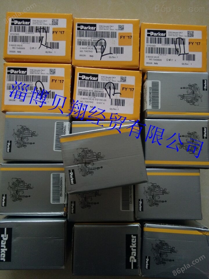
QQ交谈H111C2现货Parker电磁阀线圈 H111C2
- 公司名称:
- 更新时间:
- 所 在 地:
- 生产地址:
- 浏览次数:
- 淄博贝翔经贸有限公司
- 2017-09-15 12:22:41
- 淄博市
- 德国
- 1616
![]()
【简单介绍】
【详细说明】
Parker电磁阀线圈 H111C2
Skinner Valve
The Skinner Valve Actuation Series of solenoid valves includes the new 7700 and 7300 Lines of 3- and 4-way valves, as well as: All-Ports-In-Body valves; Intrinsically Safe valves; Quick Parker电磁阀线圈 H111C2 Exhaust valves; Direct Mount valves with NAMUR interface; Ultra Low-Power valves; and a host of accessories 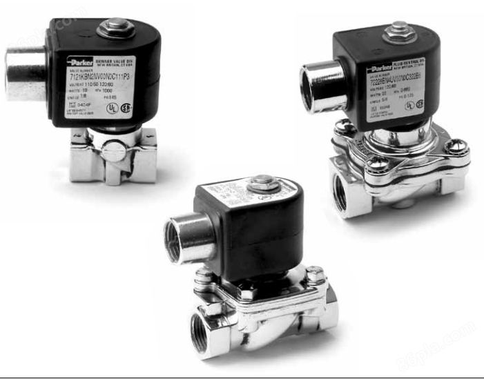 and options. In addition, to satisfy the most stringent environmental demands, most valves are available in a choice of body materials including brass, stainless steel, aluminum and others, as well as a variety of elastomeric seals.
7700 Line
parker电磁阀,parker电磁阀,美国parker电磁阀parker电磁阀,parker电磁阀,美国parker电磁阀
PARKER/PARKER电磁阀/PARKER气缸/PARKER气动元件
1/4” 7700 Line–Externa 11/64 1/4 l Pilot* 0.55 1.2 30 30 150 150 150 150 150 150
77317BN2KN7M 77317BN2PN7M 77317VN2KN7M 77317VN2PN7M 1 1
1/4” 11/64 1/4 0.55 1.2 0 0 150 150 150 150 150 150
78317BN2KN7M 78317BN2PN7M 78317VN2KN7M 78317VN2PN7M 2 2
* External pilot pressure to operate valve must be 30-150 PSI.
7300
SKINNER 7300 LINE FEATURES
7300 Line
1/4” 11/64 0.55 30 150 150 150 150 73317BN2KN00 73317VN2KN00 3
1/4 1.2 30 150 150 150 150 73317BN2PN00 73317VN2PN00 3
7300 Line–External Pilot*
1/4” 11/64 0.55 0 150 150 150 150 74317BN2KN00 74317VN2KN00 4
1/4 1.2 0 150 150 150 150 74317BN2PN00 74317VN2PN00 4
7300 Line– 4.0 Cv, Single Solenoid
1/2” 5/8 4.0 30 150 150 150 150 73317BN4UN00 - 29A
7300 Line– 4.0 Cv, External Pilot
1/2” 5/8 4.0 30 150 150 150 150 74317BN4UN00 - 29A
7300 Line –4.0 Cv, Remote Pilot
1/2” 5/8 4.0 30 150 150 150 150 75317BN4UN00 - 29A
Operating Pressure Differential (PSI)
Pipe Orifice Cv Brass Stainless Steel
Size Size Flow Pressure Vessel Pressure Vessel Constr.
(NPT) (Inches) Factor Min Maximum Catalog Number Catalog Number Ref.
SPECIFICATIONS
Mechanical Characteristics:
Standard Materials of Construction
S p r i n gs–Stainless Steel (18-8 or 17-4)
●
F i l t er– P o l y e t h y l e n e
Catalog Number Catalog Number Ref.
7300 Line-Remote Operate**
1/4” 11/64 0.55 30 150 75317BN2KN00 5
1/4 1.2 30 150 75317BN2PN00 5
* External pilot pressure to operate valve must be 30-150 PSI. **Remote pilot pressure to operate valve = 35 PSI + .2 (main line pressure)
1 0
SKINNER 7000 SERIES THREE-WAY VA LV E S
Pipe Size (NPT) Orifice Size (Inches) Cv Flow Factor Operating Pressure Differential (PSI) Brass Pressure Vessel Catalog Number Stainless Steel Pressure Vessel Catalog Number Constr. Ref.
Min Maximum
AC DC
10 watt 22 watt 10 watt
Normally Closed
1/8” 1/4”
3/8” 1/2” 3/4”
1/16 3/32 1/16 1/16 3/32 5/64 3/32 3/8 1/2 3/4 0.11 0.24 0.11 0.11x 0.095 0.17 .17x .24 0.24 2.1 3.6 7.3 0 0 0 0 0 0 0 10 10 10
215 100 215 200 125 150 100 180 180 180 215 100 215 200 125 150 100 180 180 180 7131KBN1GV00 7131KBN1LV00 7131KBN2GV00
7131KBN2JV00 7131KBN2LV00 73312BN3RNJ1 73312BN4UNJ1 73312BN52NJ1
71315SN2GNJ1 71315SN2KNJ1
6 6 6 7 7 6 6 9 9 9
Continues on next page.
SKINNER 7000 SERIES THREE-WAY VA LV E S
Pipe Size (NPT) Orifice Size (Inches) Cv Flow Factor Operating Pressure Differential (PSI) Brass Pressure Vessel Catalog Number Stainless Steel Pressure Vessel Catalog Number Constr. Ref.
Min Maximum
AC DC
10 watt 22 watt 10 watt
Normally Open
1/8” 1/4” 3/8” 1/2” 3/4” Multipurpose 1/16x 1/8 3/32x 1/8 1/16x 1/8 1/16x 1/8 3/32x 1/8 3/8 3/8 1/2 3/4 0.10x 0.28 0.17x 0.28 0.10x 0.28 0.10x 0.28 0.17x 0.28 2.1 2.1 3.6 7.3 0 0 0 0 0 10 10 10 10 150 125 150 150 125 180 180 180 180 150 125 150 150 125 180 180 180 180 73322BN3RNJ1 73382BN3RNJ1 73322BN4UNJ1 73322BN52NJ1 71395SN1GVJ1 71395SN1KVJ1 71395SN2GNJ1 71395SN2GVJ1 71395SN2KNJ1 7 7 7 7 7 9 9 9 9
1/8” 1/4” All-Ports-In-Body, 1/16 5/64 3/64 1/16 1/16 5/64 3/32 3/32 Normally Closed 0.11 0.15 0.052 0.095 0.11 0.15 0.17 0.24 0 0 0 0 0 0 0 0 150 100 180 115 150 100 80 60 150 100 180 115 150 100 80 60 7133KBN1GVJ1 7133KBN1JVJ1 7133KBN2GVJ1 7133KBN2JVJ1 7133KBN2LVJ1 71335SN2ENJ1 71335SN2GNJ1 71335SN2KNJ1 6 6 7 7 6 6 7 6
1/4” All-Ports-In-Body, 1/16 5/64 5/6x 1/8 3/32 3/32x 9/64 1/8 1/4 Normally Open 0.095 0.14 0.14x 0.31 0.19 0.19x 0.38 0.31 .49x .63 0 0 0 0 0 0 0 200 150 150 120 120 70 30 200 150 150 120 120 70 30 7131TBN2JV00 7131TBN2LV00 7131TBN2RV00 7131TVN2GV00 7131TVN2JV00 7131TVN2LV00 7131TVN2NV00 10 10 11 10 11 10 11
1/4” All-Ports-In-Body, 5/32x 1/8 Multipurpose 0.41x 0.31 0 150 7132TBN2NV00 11
1/4” Normally Closed,Q 1/16 5/64 5/64 1/8 1/8 uick Exhaust* 0.095 0.17 0.18 0.31 0.32 0 0 0 0 0 150 100 100 30 30 150 100 100 30 30 7133TBN2JV00 7133TBN2NV00 7133TVN2GV00 7133TVN2JV00 7133TVN2NV00 10 11 10 11 10
1/4” 3/32x 1/8 1/4 0.11x 0.35 0.2x 1.1 0 0 125 100 125 100 7131EBN2LN00 71313SN2KNJ1 8 12
*The valves operate at 0 PSI, however a 2 PSI minimum pressure differential is required to actuate the pressure operated quick exhaust poppet.
F o u r- Way Va l v e s
Skinner Valve Actuation Series F o u r-Way
Solenoid Valves
Skinner four-way solenoid valves are ideal for use in controlling double acting, pneumatic actuators or cylinders. Two-position, single or double solenoid models are designed for long, trouble-free life, and are available in 7700 Line, 7300 Line, and standard solenoid valves.
F o u r-way 7700 and 7300 Line valves have many of the same standard features found in the line’s three-way valves, including a unique seal, spool and cage design, integral pilot filtration and contamination tolerant design. They are available in brass or 303 stainless steel body materials. Skinner 7000 Series four-way valves are available in aluminum body material. These four-way valves have a maximum pressure differential of 150 PSI, with a Cv flow factor of 0.55 or 1.2 for 7700 and 7300 Line valves and 0.35, 1 or 1.4 for 7000 Series valves.
7700
M i s c e l l a n e o u s
● C a g es– T h e r m o p l a s t i c
SKINNER 7700 ● Sleeve Tu be–Stainless Steel (304) Minimum Ambient Te m p e r a t u r e LINE FEATURES ● P l u n g er–
7700 Line
1/4” 11/64 0.55 30 150 150 150 77417BN2KN7M 77417VN2KN7M 1
1/4 1.2 30 150 150 150 77417BN2PN7M 77417VN2PN7M 1
7700 Line– Double Solenoid
1/4” 11/64 0.55 30 150 150 150 77477BN2KN7M 77477VN2KN7M 13
1/4 1.2 30 150 150 150 77477BN2PN7M 77477VN2PN7M 13
7700 Line– External Pilot*
1/4” 11/64 0.55 0 150 150 150 78417BN2KN7M 78417VN2KN7M 2
1/4 1.2 0 150 150 150 78417BN2PN7M 78417VN2PN7M 2
* External pilot pressure to operate valve must be 30-150 PSI.
Electrical Connections
SPECIFICATIONS
● Leaded, 1/2” Conduit, DIN, Screw, Ta b
Mechanical Characteristics Agency Approvals
●
U L approvals are available on valves with Standard Materials of Construction applicable coil/enclosure combinations.
●
B o dy–Brass or 303 Stainless Steel For additional information see pages 40-41 .
●
S e a ls– N B R
7300
SKINNER 7300 LINE FEATURES
Standard Features
Unique Seal, Spool and Cage Design
Integral Pilot Filtration
Contamination Tolerant Design
Captured Pusher Cavity Exhaust
A i r-Assisted Spring Return
Tag Mount Provision
1.5 Watt Power Level
Optional Features
Captured Exhaust Pilot
Horizontal Oriented Solenoid Operators
M o m e n t a ry or Field Convertible Manual Overrides
Exhaust Adaptors
7300 Line 1/4” 11/64 0.55 1/4 1.2 7300 Line–Double Solenoid 1/4” 11/64 0.55 1/4 1.2 7300 Line– External Pilot* 1/4” 11/64 0.55 1/4 1.2 7300 Line– 4.0 Cv, Single Solenoid 1/2” 5/8 4.0 7300 Line–4.0 Cv, Double Solenoid 1/2” 5/8 4.0 7300 Line –4.0 Cv, Single Solenoid External Pilot 1/2” 5/8 4.0 7300 Line– 4.0 Cv, Single Solenoid Remote Pilot 1/2” 5/8 4.0 30 30 30 30 0 0 30 30 30 30 150 150 150 150 150 150 150 150 150 150 150 150 150 150 150 150 150 150 150 150 150 150 150 150 150 150 150 150 150 150 150 150 150 150 150 150 150 150 150 150 73417BN2KN00 73417BN2PN00 73477BN2KN00 73477BN2PN00 74417BN2KN00 74417BN2PN00 73417BN4UN00 73477BN4UN00 74417BN4UN00 75417BN4UN00 73417VN2KN00 73417VN2PN00 73477VN2KN00 73477VN2PN00 74417VN2KN00 74417VN2PN00 ---- 3 3 14 14 4 4 29A 29A 29A 29A
Pipe Orifice Cv Size Size Flow (NPT) (Inches) Factor Min Operating Pressure Differential (PSI) Maximum Brass Pressure Vessel Catalog Number Stainless Steel Pressure Vessel Catalog Number Constr. Ref.
●
S p o ol– T h e r m o p l a s t i c
●
C a g es– T h e r m o p l a s t i c
●
Sleeve Tu be–Stainless Steel (304)
●
P l u n g er–Stainless Steel (430 FR)
●
S t op–Stainless Steel (430 FR)
●
S p r i n gs–Stainless Steel (18-8 or 17-4)
●
F i l t er– P o l y e t h y l e n e
Compatible Fluids
● Lubricated A i r, Non-Lubricated A i r, Inert Gases and other gases compatible with materials of construction.
Electrical Characteristics
Vo l t a g e s
●
DC–12, 24, 48
●
AC–24/60, 11 0 / 50-120/60, 220/50-240/60 (other voltages available upon request)
M i s c e l l a n e o u s
Minimum Ambient Te m p e r a t u r e
● -4 0 ° F (-4 0 ° C ) Dew point must be more than 7°F below a m b i e n t .
Maximum Ambient Te m p e r a t u r e
●
1.5 Wa tt–150°F (65°C)
●
10 Wa tt–167°F (75°C)
●
F l u x t r o n / M a g n e l a t ch– 1 2 2 ° F ( 5 0 ° C )
Maximum Fluid Te m p e r a t u r e
● 167°F (75°C)
Mounting Position
● M u l t i p o i s ed–valves may be installed in any position.
SKINNER 7300 LINE FOUR-WAY VA LV E S Operating Pressure Differential (PSI) Pipe Orifice Cv Maximum Size Size Flow AC DC (NPT) (Inches) Factor Min. 1.5 watt 10 watt 1.5 watt 10 watt Brass Pressure Vessel Catalog Number Stainless Steel Pressure Vessel Catalog Number Constr. Ref.
7300 Line– Remote Operate**
1/4” 11/64 0.55 30 150 75417BN2KN00 5
1/4 1.2 30 150 75417BN2PN00 5
*External pilot pressure to operate valve must be 30-150 PSI. * *Remote pilot pressure to operate valv e = 35 PSI+ .2 (main line pressure)
1 5
7000
SPECIFICATIONS
Mechanical Characteristics
Standard Materials of Construction
●
B o dy– A l u m i n u m
●
S e a ls– N B R
●
S p o ol– A l u m i n u m
●
Sleeve Tu be–Stainless Steel (304)
●
P l u n g er–Stainless Steel (430 FR)
●
S t op–Stainless Steel (430 FR)
●
S p r i n gs–Stainless Steel (18-8)
●
Shading Ring–C o p p e r
Compatible Fluids
● Lubricated A i r, Non-Lubricated A i r, Inert Gases
Electrical Characteristics:
Vo l t a g e s
●
DC–12, 24, 48
●
AC–24/60, 110/50-120/60, 220/50-240/60 (other voltages available upon request)
Electrical Connections
● Leaded, 1/2” Conduit, DIN, Screw, Ta b
Agency Approvals
● U L approvals are available on valves with applicable coil/enclosure combinations. For additional information see pages 40-4 1 .
M i s c e l l a n e o u s
Maximum Ambient Te m p e r a t u r e
●
10 Wa tt–150°F (65°C)
●
F l u x t r o n / M a g n e l a t ch–122°F (50°C)
Mounting Position
● M u l t i p o i s ed–valves may be installed in any position.
Maximum Fluid Te m p e r a t u r e
● 167°F (75°C)
SKINNER 7000 SERIES FOUR-WAY VA LV E S
Pipe Size (NPT) Orifice Size (Inches) Cv Flow Factor Operating Pressure Differential (PSI) Aluminum Pressure Vessel Catalog Number Constr. Ref.
Min. Maximum
AC DC
10 watt 10 watt
4-Way
1/8” 5/32 0.35 15 150 150 7341LAN1HNM0 15
1/4” 15/64 1 30 150 150 73419AN2NN00 16
15/64 1 30 150 150 73419AN2NNM0 16
5/16 1.4 15 150 150 7341LMN2NNM0 17
Intrinsically Safe Va l v e s
Skinner I n t r i nsically Safe
Solenoid Valve s
Skinner Valve has long served industry with innovative valve solutions and safety related products. Skinner Intrinsically Safe solenoid valves are specifically designed for use in hazardous locations where fire or explosion hazards exist due to the presence of flammable gases, vapors, liquids, combustible dust, or easily ignitable fibers or flyings.
When used in conjunction with approved safety barriers, Skinner Intrinsically Safe valves have Factory Mutual Research and Canadian Standards Association approval for locations classified as Class I, Division I, Groups A, B, C, D; Class II, Division I, Groups E, F, G; and Class III, Division I. As part of an intrinsically safe system, the valves are incapable of causing explosive atmospheres to ignite by spark or thermal effect during normal operation or under fault conditions.
The three-way valves are offered as normally closed or multipurpose, while the four-way valves are two-position, single or double solenoid.
Six special purpose valves are also in our portfolio. Five designs with NAMUR interface can be mounted directly to actuators to save installation cost. ANo-Voltage-Release manual reset device is available for applications where human interaction is required to ensure the highest degree of safety.
SPECIFICATIONS Electrical Characteristics:
Agency Approvals
I ntri n s i c a l l y
● FMRC and CSAapprovals are available
Mechanical Characteristics
on valves with applicable coil/enclosure Standard Materials of Construction combinations. Valves starting with a 7,
● B o dy–Brass, Stainless Steel or A l u m i n u m FMRC approval only.
Safe Va l v e s
●
S e a ls–NBR, FKM
●
S p o ol– T h e r m o p l a s t i c
M i s c e l l a n e o u s
●
C a g es– T h e r m o p l a s t i c
●
Sleeve Tu be–Stainless Steel (304) Ambient Te m p e r a t u r e
●
P l u n g er–Stainless Steel (430 F) ● -40°F to 150°F (-40°C to 65°C), see chart
●
S t op–Stainless Steel (430 F) Temperature ranges are dictated by the
●
S p r i n gs–Stainless Steel (18-8) specific coil/pressure vessel combinations.
Compatible Fluids Fluid Te m p e r a t u r e
● Lubricated A i r, Non-Lubricated A i r, ● -40°F to 167°F (-40°C to 75°C), see chart
Inert Gases Mounting Position
● M u l t i p o i s ed–valves may be installed in any position.
3-Way
1/4” 5/128 0.04 0 150 +14 to 150 +14 to 167 Brass U131K0490 18
5/128 0.04 0 150 +14 to 150 +14 to 167 316L S.S. U131V5490 19
3/64 0.06 0 100 +14 to 150 +14 to 167 Brass U131K0890 18
3/64 0.06 0 100 +14 to 150 +14 to 167 316L S.S. U131V5890 19
13/64 0.5 0 150 -13 to 150 -13 to 167 316LS.S. U133X5196* 20
1/4 1.2 30 150 +14 to 150 +14 to 167 Brass 73317BN2PN90 21
3-Way –4.0 Cv, Single Solenoi d
1/2” 5/8 4.0 30 150 +14 to 150 +14 to 167 Brass 73317BN4UN90 8A
5/8 4.0 30 150 -40 to 150 -40 to 167 Brass 73317BN4U9C 8A
3-Way – Manua l Reset
1/4” 4-Way 13/64 0.5 0 150 -13 to 150 -13 to 167 316L S.S. U033X5156* 22
1/4” 11/64 0.55 30 150 +14 to 150 +14 to 167 Brass 73417BN2KN90 21
11/64 0.55 30 150 +14 to 150 +14 to 167 303 S.S. 73417VN2KN90 21
1/4 0.7 15 150 +14 to 150 +14 to 167 Alum. U341B3490 23
1/4 1.2 30 150 +14 to 150 +14 to 167 Brass 73417BN2PN90 21
1/2” 9/16 4 7 150 +14 to 150 +14 to 167 Alum. U341L2190 24
4-Way– 4.0 Cv, Single Solenoi d
1/2” 5/8 4.0 30 150 +14 to 150 +14 to 167 Brass 73417BN4UN90 8A
5/8 4.0 30 150 -40 to 150 -40 to 167 Brass 73417BN4UN9C 8A
4-Way, Double Solenoid
1/4” 11/64 0.55 30 150 +14 to 150 +14 to 167 303 S.S. 73477VN2KN90 25
1/4 1.2 30 150 +14 to 150 +14 to 167 Brass 73477BN2PN90 25
4-Way –4.0 Cv, Double Soleno id
1/2” 5/8 4.0 30 150 +40 to 150 +14 to 167 Brass 73477BN4UN90 8A
5/8 4.0 30 150 -40 to 150 -40 to 167 Brass 73477BN4U9C 8A
NAMUR 3/4-W ay
1/4” 11/64 0.55 30 150 +14 to 150 +14 to 167 Alum. 73417AKDKN90 26
1/4 1.2 30 150 +14 to 150 +14 to 167 Alum. 73417AKDPN90 26
NAMUR 3/4-W ay, Double Solenoid
1/4” 11/64 0.55 30 150 +14 to 150 +14 to 167 Alum. 73477AKDKN90 27
1/4 1.2 30 150 +14 to 150 +14 to 167 Alum. 73477AKDPN90 27
*Requires coil 490860N7
Intrinsically Safe Solenoid Va l v e s
S k i n n e r’s Intrinsically Safe valve off e r i n g contains five different coil designs to allow the selection of the optimum coil configuration for the application. Each coil is built to meet NEMA4 Wa t e r t i g h t construction, and has a T6 temperature classification. If the use of electrical conduit is preferred, 1/2” NPTconduit hub adaptors may be ordered for field i n s t a l l a t i o n .
I N T R I N S I C A L LY SAFE SOLENOIDS
Solenoid Minimum Total Ambient Factory Mutual
Part Number Nominal Voltage Operating Current* Solenoid Resistance Temperature Range Entity Parameters
Vmax Imax Ci Li
Splice Box Coil Enclosure
490885 Potted Coil With Le 24 VDC ad Wires 29 mA 345 Ohms -13 to +150 30 V 100 mA 0 microF 0 mH
490890 Potted Coil With DI 24 VDC N Connection 29 mA 345 Ohms -13 to +150 30 V 100 mA 0 microF 0 mH
490895 32mm DIN Coil And 24 VDC Plug Adaptor 29 mA 345 Ohms -13 to +150 30 V 100 mA 0 microF 0 mH
490880 Splice Box Coil Enc 24 VDC losure with Booster 35 mA Circuit 340 Ohms -13 to +130 30 V 100 mA 0 microF 0 mH
490860** 24 VDC. 60 mA 23 Ohms -13 to +150 Loop Approval only. Consult factory.
* These are the currents at which a complete assembly (coil and pressure vessel) will operate. ** For use on U133X5196 only.
To Order a Complete I.S. Va l v e :
1 . Select the base valve which meets the application requirements.
2 . Select the desired coil/enclosure combination.
3 . Delete the first two digits of the coil part number.
Splice Box Coil Enclosure 490885
Div. I; Class I, II, III; Groups A-G U22-002 4 . For valves that start with a 7, add N0 to catalog number.
Potted Coil With Lead Wires 490890 Div. I; Class I, II, III; Groups A-G U22-003 5 . Add the remaining four digits of the coil number to the end of the base valve number.
Potted Coil With DIN Connection 490895 Div. I; Class I, II, III; Groups A-G U27-001 6 . Add the voltage code N7 to the number.
32mm DIN Coil And Plug Adaptor 490880 (FMRC only)
Div. I; Class I, II, III; Groups C-G U27-001
Splice Box Coil Enclosure with Booster Circuit 490860
Div. I; Class I, II, III; Groups C-G U22-001
1 9
Ultra Low-Power
Skinner Ultra Low-Power
Va l v e s
Solenoid Valves
S k i n n e r’s Ultra Low-Power solenoid valves use a unique operator designed to keep current draw to a minimum by controlling the stroke, and conventional coil construction to achieve a power consumption level of 0.6 watts with no refresh time required. These valves are ideally suited for use in automated control systems, applications where minimizing energ y consumption is critical or where heat rise in the coil must be kept to a minimum. These devices allow for an increased number of solenoids to be driven from the same power source, reducing the overall installation cost.
The coils come in an integrated design in both NEMA 4X and NEMA 4X, 7 and 9 versions.
Vo l t a g e s
SPECIFICATIONS
● DC–12, 24, 48
U l t r a
Mechanical Characteristics Electrical Connections
● 1/2” Conduit
Standard Materials of Construction
Agency Approvals
● B o dy–Brass or 303 Stainless Steel
L o w - P o w e r
● U L approvals are available on valves with
● S e a ls– N B R
SKINNER 7300 LINE FEATURES
Standard Features
Unique Seal, Spool and Cage Design
Integral Pilot Filtration
Contamination Tolerant Design
Captured Pusher Cavity Exhaust
A i r-Assisted Spring Return
Tag Mount Provision
1.5 Watt Power Level
Optional Features
Captured Exhaust Pilot
Horizontal Oriented Solenoid Operators
M o m e n t a ry or Field Convertible Manual Overrides
Exhaust Adaptors
0.6 Wa t t s
3-Way 1/4” 5/128 0.04 7300 Line – 3-Way 1/4” 11/64 0.55 1/4 1.2 7300 Line 4.0 Cv, Single Solenoid 1/2” 5/8 4.0 7300 Line – 4-way 1/4” 11/64 0.55 1/4 1.2 7300 Line 4.0 Cv, Single Solenoid 1/2” 5/8 4.0 7300 Line – 4-Way, Double Solenoid 1/4” 11/64 0.55 1/4 1.2 7300 Line 4.0 Cv, Double Solenoid 1/2” 5/8 4.0 0 150 30 150 30 150 30 150 30 150 30 150 30 150 30 150 30 150 30 150 7131KBN2EV90 73317BN2PN90 73317BN4UN90 73417BN2PN90 73417BN4UN90 73477BN2PN90 73477BN4UN90 7131KVN2EV90 73317VN2KN90 -73417VN2KN90 -73477VN2KN90 - 18/19 21 21 29A 21 21 29A 25 25 29A
Pipe Orifice Cv Size Size Flow (NPT) (Inches) Factor Operating Pressure Differential (PSI) Minimum Maximum Aluminum Pressure Vessel Catalog Number Stainless Pressure Vessel Catalog Number Constr. Ref.
●
S p o ol– T h e r m o p l a s t i c
●
C a g es– T h e r m o p l a s t i c
●
Sleeve Tu be–Stainless Steel (304)
●
P l u n g er–Stainless Steel (430 F)
●
S t op–Stainless Steel (430 F)
●
S p r i n gs–Stainless Steel (18-8 or 17-4)
●
F i l t er– P o l y e t h y l e n e
Compatible Fluids
● Lubricated A i r, Non-Lubricated A i r, Inert Gases and other gases compatible with materials of construction.
Electrical Characteristics
Power Consumption
applicable coil/enclosure combinations. For additional information see pages 40-41.
M i s c e l l a n e o u s
Minimum Ambient Te m p e r a t u r e
● + 1 4 ° F ( - 1 0 ° C ) Dew point must be more than 7°F below a m b i e n t .
Maximum Ambient Te m p e r a t u r e
● 140°F (60°C)
Maximum Fluid Te m p e r a t u r e
● 167°F (75°C)
Mounting Position
● M u l t i p o i s ed–valves may be installed in any position.
.
SKINNER ULTRA LOW-POWER VA LV E S Operating Pressure Differential (PSI) Pipe Orifice Cv Size Size Flow (NPT) (Inches) Factor Minimum Maximum Brass Pressure Vessel Catalog Number Stainless Steel Pressure Vessel Catalog Number Constr. Ref.
7300 Line – 4-Way, Direct Mount
1/4”
11/64 0.55
30
150
73417AKDKN90
26 1/4
1.2
30
150
73417AKDPN90
26
7300 Line – 4-Way, Double Solenoid,Direct Mount
1/4”
11/64 0.55
30
150
73477AKDKN90
27 1/4
1.2
30
150
73477AKDPN90
27
2 1
Manual Reset
Skinner Manual Re s e t
Va l v e s
Solenoid Valves
Skinner Manual Reset solenoid valves are often specified when safety is the highest concern. Typical applications include chemical processing plants, oil drilling platforms, refineries, and fuel dispensing stations. These special purpose valves act as “fluid circuit breakers” in a control system.
Skinner Manual Reset valves are available in either Electrically Tripped or No-Voltage-Release models. To operate an Electrically Tr i p p e d Manual Reset valve, the coil is de-energized and the hand lever is manually moved to the latched position. The movement of the handle causes the valve to shift. When the coil is energized, the handle and latching mechanism are automatically tripped allowing the valve to return to its original position.
In the case of No-Voltage-Release Manual Reset valves, the coil is first energized and then the hand lever is manually moved to the latched position. The movement of the handle causes the valve to shift. When the coil is de-energized, the handle and latching mechanism are automatically tripped allowing the valve to return to its original position.
The three-way Manual Reset valves are offered in normally open, normally closed and multipurpose configurations. Four-way Manual Reset valves are provided with five ports for separate control of the actuator exhaust air.
S e a ls–NBR, FKM
P l u n g er–Stainless Steel (430 FR)
S p r i n gs–Stainless Steel
M a n u a l
R e s e t ● S t op–Stainless Steel (430 FR)
● Sleeve tube–Stainless Steel (304)
Compatible Fluids
● Determined by valve selection. Most valves are compatible with inert gases, air, and petroleum products. Consult factory.
SPECIFICATIONS
● 10 Wa t ts– A C
Electrical Characteristics Mechanical Characteristics Power Consumption Standard Materials of Construction
● 22 Wa t ts– D C
●
B o dy–Brass, Stainless Steel or A l u m i n u m as specified Vo l t a g e s
●
Manual Reset Housing–B r a s s ● AC–24/60, 110/50-120/60, 2 2 0 / 5 0 - 2 4 0 / 6 0
SKINNER MANUAL RESET VA LV E S
Pipe Orifice Cv Operating Pressure Max No Voltage Electrically
Size (NPT) Size (Inches) Flow Factor Differential(PSI) Fluid Temp (°F) Release Pressure Vessel Tripped Pressure Vesse
Min AC Max DCMax
3-Way Normally Closed,Brass Body, NBR Seals
● DC–12, 24, 48
Electrical Connections
● Leaded, DIN, 1/2 conduit, Screw, Ta b s
Agency Approvals
● U L approvals are available on valves with applicable coil/enclosure combinations. For additional information see pages 40-41.
M i s c e l l a n e o u s
Maximum Fluid Te m p e r a t u r e
● 185°F (85°C)
Maximum Ambient Te m p e r a t u r e
●
10 Wa tt–167°F (75°C)
●
22 Wa tt–131°F (55°C)
1/4” 11/64 0.55 30 150 150 165 70317BN2KNVR 70317BN2KNET
1/4 1.2 30 150 150 165 70317BN2PNVR 70317BN2PNET
3/8” 3/8 2.1 10 180 180 185 70312BN3RNVR 70312BN3RNET
1/2” 1/2 3.6 10 180 180 185 70312BN4UNVR 70312BN4UNET
3/4” 3/4 7.3 10 180 180 185 70312BN52NVR 70312BN52NET
3-Way Normall y Closed,Stainle ss Steel Body, N BR Seals
1/4” 3/64x 3/32 0.62x .017 0 200 200 185 70315SN2ENVR 70315SN2ENET
1/8x 3/32 0.23x 0.17 0 200 200 185 70315SN2ENVR 70315SN2MNET
11/64 0.55 30 150 150 165 70317VN2KNVR 70317VN2KNET
1/4 0.55 30 150 150 165 70317VN2PNVR 70317VN2PNET
3-Way Normall y Closed,Stainle ss Steel Body, F KM Seals
1/4” 1/16x 3/32 0.11x 0.17 0 150 150 185 70315SN2GVVR 70315SN2GVET
3/32x 3/32 0.17x 0.17 0 90 90 185 70315SN2KVVR 70315SN2KVET
3-Way Normall y Open,Brass or Stainless Steel Body, NBR Seal s
1/4” 1/16x 3/32 0.095x 0.17 0 150 150 185 70325SN2GNVR 70325SN2GNET
3/8” 5/8 2.1 10 180 180 185 70322BN3RNVR 70322BN3RNET
1/2” 1/2 3.6 10 180 180 185 70322BN4UNVR 70322BN4UNET
3/4” 3/4 7.3 10 180 180 185 70322BN52NVR 70322BN52NET
3-Way Universa l All-Ports In Bo dy, Brass Body, NBR Seals
1/4” 5/64x 5/64 0.17x 0.17 0 100 100 185 7033TBN2JVVR 7033TBN2JVET
1/8x 1/8 0.23x 0.23 0 50 50 185 7033TBN2NVVR 7033TBN2VVET
3-Way Universa l All-Ports In Bo dy, 303 Stainles s Steel Body, FKM Seals**
1/4” 1/16x 1/16 .095x 0.09 0 150 150 185 7033TVN2GVVR 7033TVN2GVET
5/64x 5/64 0.17x 0.17 0 100 100 185 7033TVN2JVVR 7033TVN2JVET
1/8x 1/8 0.23x 0.23 0 50 50 185 7033TVN2NVVR 7033TVN2NVET
3-Way Intrinsic ally Safe, Stainle ss Steel Body, N BR Seals
1/4” 4-Way, Aluminu 3/16 m Body, NBR S 0.63 eals 0 145 145 135 U033X51560860N7*
1/4” 4-Way, Brass B 1/4 ody, NBR Seals 1 15 150 150 165 70419AN2NNVR 70419AN2NNET
1/4” 11/64 0.55 30 150 150 165 70417BN2KNVR 70417BN2KNET
1/4 1.2 30 150 150 165 70417BN2PNVR 70417BN2PNET
4-Way, Stainles s Steel Body, NBR S eals
1/4” 11/64 0.55 30 150 150 165 70417VN2KNVR 70417VN2KNET
1/4 1.2 30 150 150 165 70417VN2PNVR 70417VN2PNET
Direct Mount (NAMUR patterned) Va l v e s
Skinner Direct Mo u n t Solenoid Valves
For Direct-Mount solenoid valves, it is important to define the exact locations of the process connections, mounting screws, and so on, to achieve proper valve function and adequate sealing.
I n c r e a s i n g l y, actuator manufacturers are utilizing a standardized mounting pattern referred to as the NAMUR interface. In addition to defining the critical dimensions and locations, the NAMUR interface pattern includes two M5 mounting screws, an M5 positioning stud, and two 1 6 m m x 2mm O-rings as standard.
Three-way Skinner NAMUR valves are normally closed, direct acting models.
The four-way Skinner NAMUR valve designs have a Cv range from .55 to 1.2, and are supplied with a unique 3-way/4-way conversion plate. The user can alter the function of the valve from 4-way to 3-way simply by rotating the conversion plate 180 degrees. In the 3-way configuration, the plate channels return air from the piston side to the spring cavity of the a c t u a t o r. Without this venting feature, environmental air–which is often contaminated with moisture, dust particles, or other particulates–would be drawn into the spring cavity promoting spring corrosion and premature actuator failure.
F i l t er– P o l y e t h y l e n e
P l a te– T h e r m o p l a s t i c
Direct Mount
Compatible Fluids
Lubricated A i r, Non-Lubricated A i r, Inert
Gases and other gases compatible with materials of construction.
Electrical Characteristics Mechanical Characteristics
Vo l t a g e s Standard Materials of Construction ● DC–12, 24, 48
B o dy–Aluminum or 303 Stainless Steel ● AC–24/60, 110/50-120/60, 220/50-240/60
S e a ls–NBR or FKM (other voltages available upon request).
S p o ol– T h e r m o p l a s t i c
Electrical Connections
C a g es– T h e r m o p l a s t i c
Leaded, 1/2” Conduit, DIN, Screw, Ta b
Mounting Position
M u l t i p o i s ed–valves may be installed in any position.
1/4” 3/32 5/64 3/32 1/8 1/8 0.17 0.14 0.19 0.31 0.31 0 0 0 0 0 150 150 120 70 120 150 150 120 70 120 71315AKDKN00 7131TVKDJV00 7131TVKDLV00 7131TVKDNV00 7131TVKDNVP0 28 29 29 29 29
7700 Line–3- Way/4-Way
1/4” 11/64 0.55 30 150 150 150 77417AKDKN00 77417VKDKN00 30
1/4 1.2 30 150 150 150 77417AKDPN00 77417VKDPN00 30
7700 Line – 3 - ouble Solenoi d
1/4” 11/64 Way/4-Way, D 0.55 30 150 150 150 77477AKDKN00 77477VKDKN00 31
1/4 1.2 30 150 150 150 77477AKDPN00 77477VKDPN00 31
7700 Line – 3- Way/4-Way, E xternal pilot
1/4” 11/64 0.55 30 150 150 150 78417AKDKN00 78417VKDKN00 30
1/4 1.2 30 150 150 150 78417AKDPN00 78417VKDPN00 30
7300 Line –3- Way/4-Way
1/4” 11/64 0.55 30 150 150 150 150 73417AKDKN00 73417VKDKN00 32
1/4 1.2 30 150 150 150 150 73417AKDPN00 73417VKDPN00 32
7300 Line –3- Way/4-Way, D ouble Solenoid
1/4” 11/64 0.55 30 150 150 150 150 73477AKDKN00 73477VKDKN00 33
1/4 1.2 30 150 150 150 150 73477AKDPN00 73477VKDPN00 33
7300 Line –3- Way/4-Way, E xternal Pilot
1/4” 11/64 0.55 30 150 150 150 150 74417AKDKN00 74417VKDKN00 32
1/4 1.2 30 150 150 150 150 74417AKDPN00 74417VKDPN00 32
* Other coil voltages available upon request, consult Skinner Valve.
The voltages identified in the table above carry agency approvals for integrated coils. See pages 40-41 for additional information. *Magnelatch Latching Coil Voltages. Other coil voltages available upon request, consult Skinner Valve.
2 9
I N T E G R ATED COIL OFFERING
Coil Code Type of Termination Holding Power Coil Description
L111 Leads 10 W Class F Molded with 18” leads
L222 Leads 10 W Class H Molded with 18” leads
L322 Leads 22 W Class H Molded with 18” leads
C111 1/2” NPT Conduit 10 W Class F Molded; NEMA 1, 2, 3, 3S, 4, 4X; 18” Lead wires
C222 1/2” NPT Conduit 10 W Class H Molded; NEMA 1, 2, 3, 3S, 4, 4X; 18” Lead wires
C322 1/2” NPT Conduit 22 W Class H Molded; NEMA 1, 2, 3, 3S, 4, 4X; 18” Lead wires
C611 1/2” NPT Conduit 1.5 W Class F Molded; NEMA 1, 2, 3, 3S, 4, 4X; 18” Lead wires
C711 1/2” NPT Conduit 0.6 W Class F Molded; NEMA 1, 2, 3, 3S, 4, 4X; 18” Lead wires
D100 DIN 10 W Class F Molded
D200 DIN 10 W Class H Molded
D300 DIN 22 W Class H Molded
H111 1/2” NPT Conduit 10 W Class F Molded; NEMA 3, 3S, 4, 4X, 7, 9; 18” Lead wires
H222 1/2” NPT Conduit 10 W Class H Molded; NEMA 3, 3S, 4, 4X, 7, 9; 18” Lead wires
H322 1/2” NPT Conduit 22 W Class H Molded; NEMA 3, 3S, 4, 4X, 7, 9; 18” Lead wires
H611 1/2” NPT Conduit 1.5 W Class F Molded; NEMA 3, 3S, 4, 4X, 7, 9; 18” Lead wires
H711 1/2” NPT Conduit 0.6 W Class F Molded; NEMA 3, 3S, 4, 4X, 7, 9; 18” Lead wires
H1S1 1/2” Conduit Stainless 10 W Class F Molded; NEMA 3, 3S, 4, 4X, 7, 9; 18” Leads Stainless Steel
H2S1 1/2” Conduit Stainless 10 W Class H Molded; NEMA 3, 3S, 4, 4X, 7, 9; 18” Leads Stainless Steel
H3S1 1/2” Conduit Stainless 22 W Class H Molded; NEMA 3, 3S, 4, 4X, 7, 9; 18” Leads Stainless Steel
H6S1 1/2” Conduit Stainless 1.5 W Class F Molded; NEMA 3, 3S, 4, 4X, 7, 9; 18” Leads Stainless Steel
H7S1 1/2” Conduit Stainless 0.6 W Class F Molded; NEMA 3, 3S, 4, 4X, 7, 9; 18” Leads Stainless Steel
S100 Screw 10 W Class F Molded
S200 Screw 10 W Class H Molded
S300 Screw 22 W Class H Molded
T100 1/4” Tab 10 W Class F Molded
CENELEC APPROVED COILS
HZ09 3-Wire Cable Gland 10 W EEx d IIC T4 (IP 65) Molded Class F, LCIE 96.D6196X, Internal and External Grounding, Cable Length: 1500mm
HZ10 3-Wire Cable Gland 10 W EEx m II T6 (IP 65) Molded Class H, LCIE 97.D6126X, Internal and External Grounding, Cable Length: 1500mm
HZ11 3-Wire Cable Gland 22 W EEx m II T6 (IP 65) Molded Class H, LCIE 97.D6126X, Internal and External Grounding, Cable Length: 1500mm
HZ12 3-Wire Cable Gland 1.5 W EEx m II T6 (IP 65) Molded Class F, LCIE 97.D6129X, Internal and External Grounding, Cable Length: 1500mm
HZ13 3-Wire Cable Gland 0.6 W EEx m II T6 (IP 65) Molded Class F, LCIE 97.D6129X, Internal and External Grounding, Cable Length: 1500mm
HZ06 Cable Connection 8 W EEx me II T3/T4 (IP 65) LCIE 92.6036X, Reinforced plastic housing, rectified diodes and varistor protection are
encapsulated, screw termination in terminal box
VZ03 Cable Connection AC: 11 W EEx e II T4 (IP 67) LCIE 86.6161X, Metal housing with encapsulated screw terminal coil, internal and external
DC: 9 W ground screws
SPECIALTY COILS*
J611 Lead Wires 1 W 2-wire, Voltage Specific, Fluxtron Electronic Coil
F611 Lead Wires 1 W 4-wire, Voltage Specific, TTL Logic Level Compatible, Fluxtron Electronic Coil
J011 Lead Wires 0 W 2-wire, Magnelatch Coil, DC Service only
G011 Lead Wires 0 W 3-wire, Magnelatch Coil, AC or DC Service
* These coils require separate enclosures. See the Enclosure Selection Chart.
Fluxtron and Magnelatch Enclosure Selections
Acoil enclosure is necessary for both Fluxtron Electronic and Magnelatch Latching coils. An enclosure serves as a flux path for Fluxtron coils, and can also serve to protect the coil and provide a means for accommodating the electrical connections. The following enclosure selection is provided to complement the integrated coil offering, and to give customers the utmost flexibility in product type and installation. The following enclosures are available:
E n c l o s u r e s
A 0: Has a 7/8-inch exit hole to accommodate a strain relief, conduit adaptor or other fitting.
B0: Has a 1/2-inch NPTthread for attachment of conduit, 1/2-inch NPT f i t t i n g or 1/2-inch BX cable.
F 0 : Ayoke. Provides no additional protection from the environment, but merely completes the magnetic flux path.
G 0 : A1/2-inch NPT hub designed to conform to watertight standards. Can accommodate conduit, 1/2-inch NPT f i t t i n g
J 0 : Has a 7/8-inch exit hole and is built to allow an internal splice.
M 1 : For Magnelatch Latching coils only, a 1/2-inch NPT hub for attachment of conduit, 1/2-inch NPTfitting or 1/2-inch BX cable.
M2: For Magnelatch Latching coils only, leads exit from the enclosure through a
Mechanical Options
Solenoid valves at times require a variety of d i fferent mechanical options to meet the specific needs of a given application. Many of these options have become common over time, others are specified infrequently.
Skinner has the ability to produce wide varieties and combinations of mechanical options. Listed are only a few of the common options we provide. If the option (or set of options) you need is not listed, please contact a company representative for a s s i s t a n c e .
Available options are denoted by the valve family to which they pertain. T h e family designator is position 5 of the pressure vessel number. To order the listed mechanical options:
1. Select the base pressure vessel number. It must have “00” in the last two digits.
2 . Confirm compatibility of the option with the Mechanical Options Ta b l e .
3 . Write the mechanical option code in place of the last two digits of the pressure vessel number. For example, a 7133TBN2JV00 with a manual override (MO) becomes 7133TBN2JVM0.
or 1/2-inch BX cable.
A0 B0 F0 G0 J0
M1 M2
Fluxtron Enclosures
Standard Connection, 7/8” exit for lead wires, NEMA 1 Conduit Connection, 1/2” NPTconduit hub, NEMA 1 Yoke Watertight, 1/2” NPTconduit hub, NEMA4X Splice Box, allows for internal splice, NEMA 1
Magnelatch Enclosures
Magnelatch, 1/2” NPT conduit hub, NEMA 1 Magnelatch, leaded with grommet connection, NEMA 1
ground connection and may be assembled to the valve at 90° intervals. Service can be performed quickly by simply unplugging
A2 Silver Shading Ring
J0 Pilot Exhaust Return Pipe
J1 Exhaust Adaptor Nut
M0 Manual Override
M0 Field Convertible Manual Override
M5 M0 with Exhaust Adaptor Nut
R0 Metering Exhaust
R1 Main Stream Metering
R2 Adjustable Bypass
7A Momentary Manual Override
7C 7Awith J1
7F Captured Exhaust Pilot
7G 7F with 7A
7H 7F with M0
2
X X X
3
X X
X X
5
X
X X
X X X X
6
X
X
X X
7 8 9LKT
the coil. An electrician is not required. T h e
X
plug comes complete with a gasket to meet N E M A specification Type 4.
X
X X X X
X X X X X
Electrical Options
The following is a description of common options available with Valve A c t u a t i o n Series coils. To order a coil with an option write the electrical option code in place of the last two digits of the coil code. T h e s e electrical options (with exception of the ground lead) are also available for sale as individual pieces (accessories). For an accessory simply order the code.
Descriptions of Electrical Options
Option Code GL: Integrated Coils with a conduit termination are available for both ordinary and hazardous location installations. Each coil type can be provided with an 18-inch ground lead.
Option Code D1: This DIN plug is equipped with a cable gland which acts as a strain relief when tightened. Within the plug are screw terminals to which the control wires are fastened. The plug provides for a Option Code D2: This DIN plug is identical to the cable gland version except that a 1/2-inch NPT conduit thread replaces the cable gland. It is ideal for attachment of flexible c o n d u i t .
Option Codes DB, TB: This option consists of a terminal box for both the screw and DIN model integrated coils. It is designed to meet NEMAType 4, 4X standards when installed. It is provided with a 1/2-inch N P T conduit thread and ground screw.
ELECTRICAL OPTIONS
Coil Option Applicable Coils
C o d e D e s c r i p t i o n Coil Ty p e s Coil Codes
GL Ground Lead Conduit Terminated C1GL, C2GL, C3GL, H1GL, H2GL, H3GL
D1 Cable Gland DIN Plug DIN D1D1, D2D1, D3D1
D2 1/2” Conduit DIN Plug DIN D1D2, D2D2, D3D2
DB* Terminal Box DIN D1DB, D2DB, D3DB,
TB* Terminal Box Screw Terminal S1TB, S2TB, S3TB
Ordering Items 1 and 2, Fully Assembled Va l v e s
Step 1: Select the appropriate Pressure
Ve s s e l .
Step 2: Use the Mechanical Options Ta b l e ,
if required, to write the option code in place
of the last two pressure vessel digits, “00”.
Step 3: Select the appropriate integrated coil
and enclosure (NO), or enclosure and
conventional coil.
Step 4: Use the Electrical Options Table, if
required, to write the option code in place of
the last two coil digits.
Step 5: Use the Voltage Code to specify the
correct voltage for the valve.
Pressure Voltage Vessel Enclosure Coil Code
7131KBN2GV00 + NO + C111 + P3 7131KBN2GV00N0C111P3
Ordering Items 3 and 4, Pressure Vessels, Integrated Coils
Pressure Vessels can be ordered as separate items. Simply select the catalog number and submit the order. If a mechanical option is desired, make sure it is included in place of the last two “00” digits in the pressure vessel number.
Integrated Coils can be ordered as separate items. Simply select the coil number and add the correct voltage code. If an electrical option is desired, make sure that it is included in place of the last two digits in the coil number, then specify the voltage by its code.
Va l v e
digit significant numbering system. This system allows the user an easy method to select and identify the product. Please note that some Skinner Intrinsically Safe valves have a different numbering system.
Numbering
Provided below is a complete set of numbering system codes. T h e codes apply to three major valve components; the pressure vessel, the enclosure, and the coil.
Skinner Ac t u a t i o n Series Nu m b e r i n g Sys t e m
77317BN2KN00
Actuation Type
7 0 – Manual Reset 1 –Direct Operated 3 – Three-Way 4 – Four-Way
3 – Pilot Operated, Internal Pilot Supply 4 – Pilot Operated ,
External Pilot Supply 5 – Remote Pressure
Operated
7 – 7700 Line, Pilot Operated, Internal Pilot Supply 8 –7700 Line, Pilot Operated,
External Pilot Supply
Flow Pattern Family Body Material
3-Way Valves 2 A – Aluminum
1 – Normally Closed 3 B – Brass
2 – Normally Open: pressure in body 5 S– 430F SS
3 – Multipurpose 6 V – 303 SS
8 – Diverting 7 M – Zinc alloy
9 – Normally Open: pressure in sleeve 9
E
4-Way Valves K
1 – 2-position, single operator, monostable L
7 – 2-position, dual operator, bistable T
X
Connection
N–NPT G–BSP PL K–Direct Mount P–NPTF
Pipe Size
For N, G, or P in Position 7:
1–1/8” 2–1/4” 3–3/8” 4–1/2” 5–3/4”
For K in Position 7: D– NAMUR
Orifice/Cv/Flow
A through H J through N P through V 0 through 9
Seals
N–NBR V–FKM
Mechanical Options
00–No Option M0–Manual Override* J1–Exhaust Adaptor Nut M5–MO & J1 ET–Electrically Tripped Manual Reset VR–No-Voltage-Release Manual Reset 7A–Momentary Manual Override 7C–7A& J1 7F–Captured Exhaust Pilot 7G–7F & 7A 7H–7F & M0 7M – Plugged Manual Override
*Field Convertible with 6 or 7 in position 5.
Enclosure Options
A0–7/8” Knock Out B0–1/2” Conduit F0–Yoke G0–Watertight J0–Junction Box M1–Magnelatch 1/2” Conduit M2–Magnelatch Grommet N0–Nut & Washer for Integrated Coils
Coil Ty p e Te r m i n a t i o n s Vo l t age
Integrated Coils
C1–1/2” NPT conduit, 10 Watt, Class F, NEMA 4X
C2–1/2” NPT conduit, 10 Watt, Class H, NEMA4X
C3–1/2” NPT conduit, 22 Watt, Class H, NEMA4X
C6–1/2” NPT conduit, 1.5 Watt, Class F, NEMA 4X
C7–1/2” NPT conduit, 0.6 Watt, Class F, NEMA4X
D1–DIN, 10 Watt, Class F
D2–DIN, 10 Watt, Class H
D3–DIN, 22 Watt, Class H
H1–1/2” NPT conduit, 10 Watt, Class F, NEMA 4X, 7, 9
H2–1/2” NPT conduit, 10 Watt, Class H, NEMA4X, 7, 9
H3–1/2” NPT conduit, 22 Watt, Class H, NEMA4X, 7, 9
H6–1/2” NPT conduit, 1.5 Watt, Class F, NEMA4X, 7, 9
H7–1/2” NPT conduit, 0.6 Watt, Class F, NEMA 4X, 7, 9
L1–18” leads, 10 Watt, Class F
L2–18” leads, 10 Watt, Class H
L3–18” leads, 22 Watt, Class H
S1–Screw Terminal, 10 Watt, Class F
S2–Screw Terminal, 10 Watt, Class H
S3–Screw Terminal, 22 Watt, Class H
T1–1/4” Tab Terminal, 10 Watt, Class F
Specialty Coils
F6–Fluxtron, 4-wire, 1 Watt
J6–Fluxtron, 2-wire, 1 Watt
J7–Fluxtron, 2-wire, 2 Watt
J0–Magnelatch, 2-wire, DC service only
G0–Magnelatch, 3-wire, AC or DC service
3 5
00–Standard DIN (No lead wires)
11– Class F coils, 18” lead wires 22–Class H coils, 18” lead wires GL–Ground wire for C1, C2, C3, H1, H2, & H3 coils D1–D1 coils with cable gland connector D2–D1 coils with 1/2” conduit connector DB–D1 coils with terminal box TB–S1, S2, S3 Coils with Terminal Box
Integrated & Magnelatch Coils*
B2–24/60*
C1–12 VDC*
C2–24 VDC*
C4–48 VDC
3N–125 VDC
P3–120/60, 110/50*
Q3–240/60, 220/50*
Q8–480/60, 440/50
Fluxtron Coils
C1–12 VDC C2–24 VDC C4–48 VDC C6–120 VDC P0–24/50-60 2W–110-120, 50/60 3W–220-240, 50/60
The table below summarizes the specific approvals obtained, which are dependent upon the combination of approved pressure vessels, coils and enclosures for both ordinary and hazardous locations.
Metallic Bodied Pressure Vessels**
Enclosure Coil* (Aluminum,Brass,Stainless Steel,Zinc)
Code Type/Option NPT Ported BSP Ported Direct Mounted
N0 C111, C222, C322
N0 C611, C711
N0 C1GL, C2GL, C3GL
N0 D1DB, D2DB, D3DB
N0 D4DB, D5DB
A0, B0, G0, J0 F611, J611 ULListed
N0 H111, H222, H322
N0 H611, H711
N0 H1GL, H2GL, H3GL
N0 S1TB, S2TB, S3TB
N0 D100, D1D1, D1D2
N0 D200, D2D1, D2D2
N0 D300, D3D1, D3D2
F0 F611, J611 ULComponent Recognized
N0 L111, L222, L322
N0 S100, S200, S300
N0 T00
70312 E.T. 70312 N.V.R. — — — — 16 20 31 32 — — — —
70315 E.T. 70315 N.V.R. 70317 E.T. — — — — — — 16 20 16 31 32 31 — — — — — —
70317 N.V.R. 70322 E.T. 70322 N.V.R. — — — — — — 20 16 20 32 31 32 — — — — — —
70325 E.T. 70325 N.V.R. 7033TE.T. — — — — — — 16 20 16 31 32 31 — — — — — —
7033TN.V.R. 70417 E.T. 70417 N.V.R. — — — — — — 20 16 20 32 31 32 — — — — — —
70419 E.T. 70419 N.V.R. — — — — 16 20 31 32 — — — —
3-Way
73312 71313 71315 — — — — — — 17 17 17 27 27 27 — — — —
7131E 7131K 7131T — — — — — — 17 17 17 31 31 35 — — 35 — — 57
7132E 7132T 7133K — — — — — — 20 17 17 32 35 31 — 35 — — 57 —
71335 7133T 71395 — — — — — — 17 17 17 27 35 27 — — — — — —
73317 73322 73382 2.1 — — 2.1 — — 17 17 17 27 27 27 — — — — — —
77317 2.1 2.1 — — — —
4-Way
73417 2.1 2.1 17 27 — —
73477 2.1 2.1 17 27 — —
73419 — — 17 27 — —
7341L — — 17 31 — —
77417 2.1 2.1 — — — —
77477 2.1 2.1 — — — —
Manual Reset
DC HOLDING CURRENT (AMPERES)
Coil Type Power Level 12 Volt 24 Volt 48 Volt
Integrated 0.6 Watt 0.05 0.025 0.013
Integrated 1.5 Watt 0.13 0.063 0.031
Integrated 10 Watt 0.81 0.41 0.2
DIN 10 Watt 0.81 0.41 0.2
Integrated 22 Watt 1.64 0.83 —
For Fluxtron and Magnelatch specialty coils, consult Honeywell for holding and inrush current values.
P O RT MARKINGS
Valve Ty p e Port Identification ANSI S y m b o l
P r e s s u r e C y l i n d e r E x h a u s t
3-Way, Normally Closed
71313 71315 7131E 7131K 7131T 73312 73317 73317BN2PN7F 74317 75317 77317 78317 3-Way, Normally 1 1 1 2 1 1 1 1 1 1 1 1 Open 2 2 2 1 2 2 2 2 2 2 2 2 3 3 3 0 3 3 3 3 3 3 3 3 1 1 2 3 1 11 3 4 5 6 7 8
7132T 71395 73322 73382 3-Way, Multipurp 3 3 3 2 ose 2 2 2 3 1 1 1 1 9 9 10 11
71335 7133K 7133T 4-Way a Pressure can be pplied to any port. 13 13 13
73417 73417BNSPN7F 73419 7341LAN 7341LMN 73477 73477BNSPN7F 74417 75417 77417 77477 78417 Intrinsically Safe 1 1 P 1 1 1 1 1 1 1 1 1 2, 4 2, 4 A, B 2, 4 2, 4 2, 4 2, 4 2, 4 2, 4 2, 4 2, 4 2, 4 3, 5 3, 5 EA, EB 3, 5 3, 5 3, 5 3, 5 3, 5 3, 5 3, 5 3,5 3, 5 15 15 16 17 18 19 20 21 22 23 24 25
U131K U131V U133X 73317 U033X 73417 U341B U341L 73477 Ultra-Low Power 2 1 Pressure 1 Pressure 1 1 P 1 1 2 can be applied at any port.2 can be applied at any port.2, 4 2, 4 B, A 2, 4 0 0 3 3, 5 3 S, R 3, 5 3 26 12 3 – 15 27 28 19
U131K U131V 73317 73417 73477 U033X 78417 2 1 1 1 1 Pressure 1 1 2 2 2, 4 2, 4 can be applied at any port.2, 4 0 0 3 3, 5 3, 5 3, 5 3 4 3 15 19 – 25
P O RT MARKINGS
Valve Ty p e Port Identification ANSI S y m b o l
P r e s s u r e C y l i n d e r E x h a u s t
Manual Reset
70312 1 2 3 –
70315 1 2 3 –
70317 1 2 3 –
70322 3 2 1 –
70325 2 1 3 –
7033T Pressure can be applied at any port. 13
70417 1 2, 3 4, 5 –
70419 P A, B EA, EB –
U033X Pressure can be applied at any port. –
Direct Mount
71315 1 2 3 1
7131T 1 2 3 1
73417 1 2, 4 3, 5 15
73477 1 2, 4 3, 5 19
74417 1 2, 4 3, 5 21
77417 1 2, 4 3, 5 23
77477 1 2, 4 3, 5 24
78417 1 2, 4 3, 5 25
Dimension
Valve H P C L W S T R J K
73312BN3RNJ1 4.89 3.98 1.96 2.97 2.62 0.65 0.59 1.44 1.22 0.91
73312BN4UNJ1 5.10 4.08 2.08 3.38 3.09 0.78 0.69 1.66 1.41 1.06
73312BN52NJ1 6.07 4.34 2.34 4.22 3.38 1.03 0.86 1.69 1.72 1.39
73322BN3RNJ1 4.89 3.98 1.96 2.97 2.62 0.65 0.59 1.44 1.22 0.91
73382BN3RNJ1 4.89 3.98 1.96 2.97 2.62 0.65 0.59 1.44 1.22 0.91
73322BN4UNJ1 5.10 4.08 2.08 3.38 3.09 0.78 0.69 1.66 1.41 1.06
73322BN52NJ1 6.07 4.34 2.34 4.22 3.38 1.03 0.86 1.69 1.72 1.39
H111C2 H111C2
相关产品
- 321F35现货321F35-2995-481865C2
- 321F35现货Parker电磁阀 321F35
- 322H36现货Lucifer电磁阀 322H36
- 322H35现货Lucifer电磁阀 322H35
- 321H35现货派克电磁阀321H35
- H111C2现货Parker电磁阀线圈 H111C2
- 7322BAN00现货派克电磁阀7322BAN00
- 7321BCV00现货Lucifer电磁阀7321BCV00
- 7321BAV00现货Lucifer电磁阀7321BAV00
- 7321BAH00现货Parker电磁阀7321BAH00
- 7322BCV00Lucifer电磁阀7322BCV00
- 7322BDN00Parker电磁阀7322BDN00
- 7322BCN00派克电磁阀7322BCN00
- 7322BIN00Parker电磁阀7322BIN00
- 7321BIN00Lucifer电磁阀 7321BIN00
- 7321BAN00Parker电磁阀7321BAN00
- 7321BCH00Lucifer电磁阀7321BCH00
- 7321BCN00派克电磁阀7321BCN00
- 7321BDN00Parker电磁阀7321BDN00
- 7321BEN00派克电磁阀7321BEN00
- 7321BFN00原装Lucifer电磁阀7321BFN00
- 7321BGN00派克电磁阀7321BGN00
请输入产品关键字:
